
Looking for a solution to automate your reversed polarity DC motor? The ZEN17 Universal Relay can add Z-Wave control to motorized awnings, shades, blinds, and motorized screens! Set up automations based on data from smart sensors, including brightness levels, temperature, and motion.
We have provided two separate diagrams below. The first illustrates how to install the ZEN17 with a reversed polarity DC motor.
Check out the instructions below to set up your ZEN17 Universal Relay for a reversed polarity DC Motor:
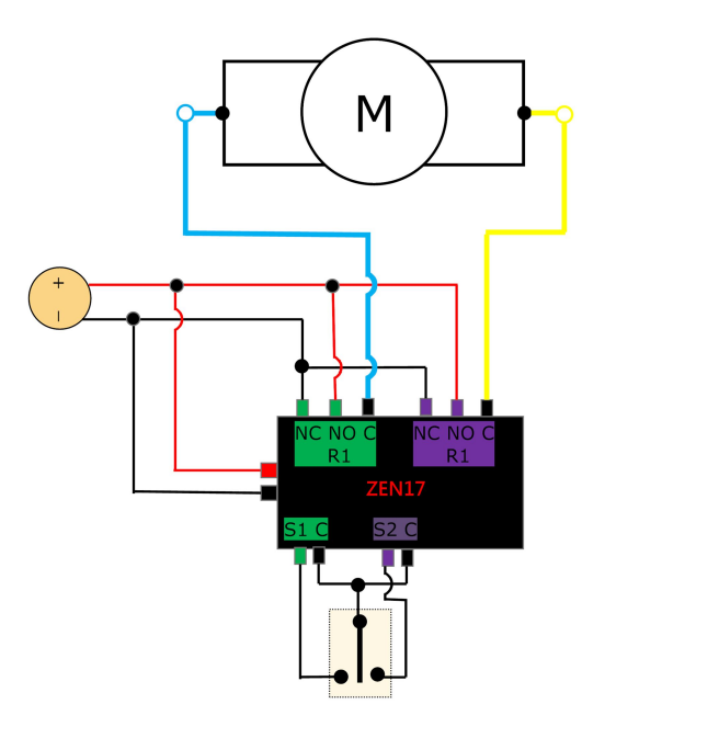
Reversed Polarity DC Motor Wiring
This wiring configuration uses both relays (R1 and R2) on the ZEN17 to reverse the polarity supplied to a DC motor, allowing control of motor direction (e.g., open/close, forward/reverse). This setup is intended for DC motors only—not AC motors. This configuration is commonly used for blinds, actuators, gates, and other applications requiring bidirectional DC motor control.
Wire the ZEN17 Universal Relay
Wiring Tips: Always take clear, detailed "before" pictures prior to installing the ZEN17. Should you ever need to restore the original set-up, or reach out to us for help, we will need to verify the original wiring to ensure the installation is correct.
-
Always use the correct screwdriver size for the terminal screws on your Universal Relay and wall switches (if connecting them).
-
Please verify you have the proper electrical tools for cutting, prepping, and stripping electrical wires.
-
If you lack the necessary tools to correctly perform the installation or are unsure which tools to use or how, please hire an electrician to complete the installation for you.
-
Please follow the National Electrical Code and your local safety regulations when performing the installation, including (but not limited to), choosing the correct gauge of jumper wires.
Power Off: Please verify you have turned off the circuit power in the breaker panel before you start installation. Keep the Universal Relay unplugged from its power source whle performing the installation.
Connect the Universal Relay:
-
The DC power supply positive (+) is fed to R1 NO and R2 NO terminals. The DC power supply positive (+) is also connected to the power '+' terminal on the ZEN17.
-
The DC power supply negative (–) is fed to R1 NC and R2 NC terminals. The DC power supply negative (-) is also connected to the power '-' terminal on the ZEN17.
-
The motor leads are connected to the R1 C and R2 C common terminals of each relay.
-
When Relay 1 (R1) is activated, one polarity is applied to the motor, causing it to rotate in one direction.
-
When Relay 2 (R2) is activated instead, the polarity is reversed, and the motor rotates in the opposite direction.
-
Both relays must never be turned ON at the same time, as this would short the power supply. Enable the Parameter 24 (DC Motor Mode) to prevent both relays from activating simultaneously (see below).
Control inputs (connect a switch, optional):
-
S1 and S2 can be connected to Single Pole Double-Throw Center-Off mechanical switch.
-
Alternatively, each relay can be controlled independently via Z-Wave commands.
Power the Universal Relay:
- Connect a dedicated low-voltage power source to the ZEN17.
- DO NOT use phone/laptop chargers or any Apply accessories with the Universal Relay.
- NEVER connect AC/DC power and USB power to the ZEN17 at the same time.
- Use a DC power supply that matches the motor’s voltage and current requirements. 20% bigger power supply than the motor is always recommended.
Program the ZEN17 Universal Relay
Here is what you need to best program your device on your Z-Wave hub:
- Add the Universal Relay to your hub: Z-Box, Home Assistant, HomeSeer, Hubitat, SmartThings, and Z-Wave General Inclusion.
- Set Parameter 24 to value 1 in the parent ZEN17 device
- This will enable DC motor mode to prevent both relays from being triggered at the same time. Follow the hub-specific steps in the following articles to access and adjust the advanced settings for the ZEN17 Universal Relay: Z-Box, Home Assistant, HomeSeer, Hubitat, SmartThings.
- Use the R1 child device to actuate one direction of the motor, and the R2 child device to actuate the other direction of the motor. Turn the child device off to stop the motor.
- Feel free to use the timer settings for each relay to automatically start and stop the motor in different positions.
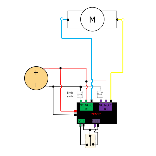
Reversed Polarity DC Motor Wiring With Limit Switches
This will be a very rare application when a DC motor does NOT have already built in limit switches. In this instance, these limit switches would need to be bought separately and wired in for additional protection on the hardware level. Most of the DC motors already have limit switches built in.
Wire the ZEN17 Universal Relay
Wiring Tips: Always take clear, detailed "before" pictures prior to installing the ZEN17. Should you ever need to restore the original set-up, or reach out to us for help, we will need to verify the original wiring to ensure the installation is correct.
-
Always use the correct screwdriver size for the terminal screws on your Universal Relay and wall switches (if connecting them).
-
Please verify you have the proper electrical tools for cutting, prepping, and stripping electrical wires.
-
If you lack the necessary tools to correctly perform the installation or are unsure which tools to use or how, please hire an electrician to complete the installation for you.
-
Please follow the National Electrical Code and your local safety regulations when performing the installation, including (but not limited to), choosing the correct gauge of jumper wires.
Power Off: Please verify you have turned off the circuit power in the breaker panel before you start installation. Keep the Universal Relay unplugged from its power source whle performing the installation.
Connect the Universal Relay:
-
The DC power supply positive (+) is fed to R1 NO and R2 NO terminals. The DC power supply positive (+) is also connected to the power '+' terminal on the ZEN17.
-
The DC power supply negative (–) is fed to R1 NC and R2 NC terminals. The DC power supply negative (-) is also connected to the power '-' terminal on the ZEN17.
-
The motor leads are connected to the R1 C and R2 C common terminals of each relay.
-
When Relay 1 (R1) is activated, one polarity is applied to the motor, causing it to rotate in one direction.
-
When Relay 2 (R2) is activated instead, the polarity is reversed, and the motor rotates in the opposite direction.
-
Both relays must never be turned ON at the same time, as this would short the power supply. Enable the Parameter 24 (DC Motor Mode) to prevent both relays from activating simultaneously (see below).
Control inputs (connect a switch, optional):
-
S1 and S2 can be connected to Single Pole Double-Throw Center-Off mechanical switch.
-
Alternatively, each relay can be controlled independently via Z-Wave commands.
Limit switch operation
-
Each motor direction has its own normally closed (NC) limit switch wired in series with the motor lead for that direction.
-
When the motor reaches its end position, the corresponding limit switch opens, cutting power to the motor and stopping movement.
-
The opposite direction remains available, allowing the motor to move away from the limit once the other relay is activated.
-
Limit switches provide hardware-level protection, independent of Z-Wave or automation logic.
Power the Universal Relay:
- Connect a dedicated low-voltage power source to the ZEN17.
- DO NOT use phone/laptop chargers or any Apply accessories with the Universal Relay.
- NEVER connect AC/DC power and USB power to the ZEN17 at the same time.
- Use a DC power supply that matches the motor’s voltage and current requirements. 20% bigger power supply than the motor is always recommended,
Program the ZEN17 Universal Relay
Here is what you need to best program your device on your Z-Wave hub:
- Add the Universal Relay to your hub: Z-Box, Home Assistant, HomeSeer, Hubitat, SmartThings, and Z-Wave General Inclusion.
- Set Parameter 24 to value 1 in the parent ZEN17 device
- This will enable DC motor mode to prevent both relays from being triggered at the same time. Follow the hub-specific steps in the following articles to access and adjust the advanced settings for the ZEN17 Universal Relay: Z-Box, Home Assistant, HomeSeer, Hubitat, SmartThings.
- Use the R1 child device to actuate one direction of the motor, and the R2 child device to actuate the other direction of the motor. Turn the child device off to stop the motor.
- Feel free to use the timer settings for each relay to automatically start and stop the motor in different positions.
Please don't hesitate to reach out to us with any questions on your installation!

