


With so many options available, let’s get to programming the ZEN12 Motion Dimmer! From scene control and multi-tap triggers to direct association, the ZEN12 offers several ways to control and automate your Z-Wave devices on the Z-Box Hub.
The ZEN12 combines a smart dimmer with built-in motion and lux sensors, three programmable physical buttons, and advanced automation capabilities. Aside from standard scenes, each button can also trigger automations through Central Scene commands, while Direct Association allows the dimmer, motion sensor, or lux sensor to control other Z-Wave devices directly. This gives you the flexibility to create advanced hub-based scenes or simple device-to-device control.
To program the multi-tap functions on the ZEN12, you can follow the standard block scene creation flow or program the scene directly from the ZEN12 device menu for a simplified and faster approach. Remember that scene control is disabled by default and must first be enabled in the ZEN12 advanced settings.
Direct association offers another way to program the ZEN12. It allows the device to send commands directly to other Z-Wave devices based on manual button operation, motion, or lux status without relying on a hub-based automation.
With either programming option, make sure you are logged in to the Z-Box WEB UI through a local connection on the same Wi-Fi network as your Z-Box Hub.
Central Scene / Scene Control
The ZEN12 Motion Dimmer supports Central Scene commands from each of its three physical buttons. Each button sends a unique Scene Number so the Z-Box can identify which button was used. The Key Attribute identifies the type of interaction, such as a single tap, double tap, hold, or release. These combinations allow each button to trigger multiple scenes or automations based on how it is pressed.
For example, a single tap of the main button could turn on the connected light, while a double tap could activate a group of lights, and a triple tap could change the operating mode of another device.
Enable Scene Control
Scene control is disabled by default on the ZEN12. Before programming the buttons, access the ZEN12 advanced settings and configure the following parameters:
-
Parameter 8: Set to
1to enable scene control. -
Parameter 40: Leave set to
0to enable multi-tap scene control.
If Parameter 40 is set to 1, only single-tap Central Scene commands will be available.
Scene Numbers and Button Mapping
Here is how the ZEN12 buttons are mapped to Central Scene scene numbers:
|
Button |
Scene Number |
Description |
|---|---|---|
|
Main Button |
|
Large on/off button |
|
Left Button |
|
Left dimming button |
|
Right Button |
|
Right dimming button |
|
ZAC99 Remote Button |
|
Optional momentary switch in a 3-way installation |
Each button supports seven Key Attributes:
|
Key Attribute |
Action Type |
|---|---|
|
|
Key Pressed Once |
|
|
Key Released |
|
|
Key Held Down |
|
|
Key Pressed 2x |
|
|
Key Pressed 3x |
|
|
Key Pressed 4x |
|
|
Key Pressed 5x |
For example:
-
Pressing the main button once = Scene 1, Key Attribute 0
-
Holding the left dimming button = Scene 2, Key Attribute 2
-
Double tapping the right dimming button = Scene 3, Key Attribute 3
The ZEN12 buttons will continue to perform their regular local functions unless physical load control has been disabled in the advanced settings. This means that pressing the main button can control the connected light while also sending a Central Scene command to the hub. Similarly, pressing and holding the left or right button can dim the connected light while sending held and released Central Scene commands.
Three taps on the main button are also used to enter Z-Wave inclusion or exclusion mode. Avoid assigning a critical action to this trigger or disable programming (inclusion/exclusion) via parameter 10.
ZEN12 + ZAC99 Momentary Switch in a 3-Way Setup
When a ZAC99 momentary switch is connected to the ZEN12 in a 3-way installation, it can report separately as Scene 4.
To enable Central Scene commands from the ZAC99, configure the following parameters:
-
Parameter 35: Set to
2for momentary-switch mode. -
Parameter 37: Set to
1to enable scene control from the remote 3-way switch. -
Parameter 8: Set to
1to enable scene control. -
Parameter 40: Leave set to
0to enable multi-tap scene control.
|
Device |
Scene Number |
|---|---|
|
ZAC99 Remote Button |
|
The ZAC99 uses the same Key Attributes as the built-in ZEN12 buttons.
For example:
-
Pressing the ZAC99 once = Scene 4, Key Attribute 0
-
Holding the ZAC99 = Scene 4, Key Attribute 2
-
Double tapping the ZAC99 = Scene 4, Key Attribute 3
This allows the Z-Box to distinguish between commands entered directly on the ZEN12 and commands entered from the remote switch location.
Summary
-
The ZEN12 uses Scenes 1–3 for its three built-in buttons.
-
Each button supports seven press actions through Central Scene Key Attributes.
-
Scene control must first be enabled through Parameter 8.
-
Parameter 40 must remain set to
0for multi-tap triggers. -
A connected ZAC99 can report separately as Scene 4 when the applicable 3-way and scene-control settings are enabled.
-
The Z-Box can create a separate automation for each supported button and press-action combination.
Central Scene Programming From the Device Menu
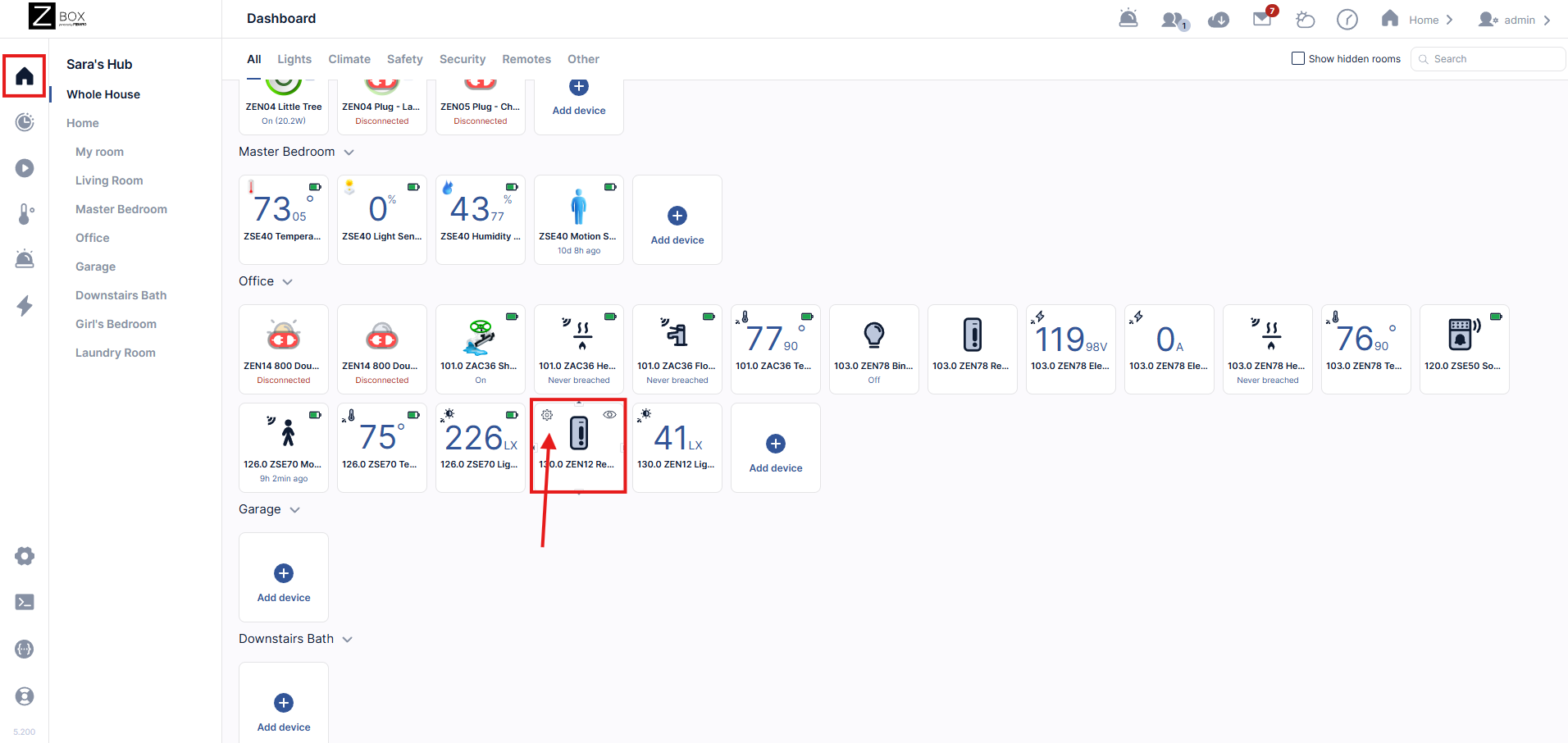
1. If you are not already on the Home Menu, open the sidebar navigation menu in the Z-Box web interface and click the house icon. Hover over the ZEN12 Motion Dimmer, then click the settings gear icon.
2. Click the Advanced tab.
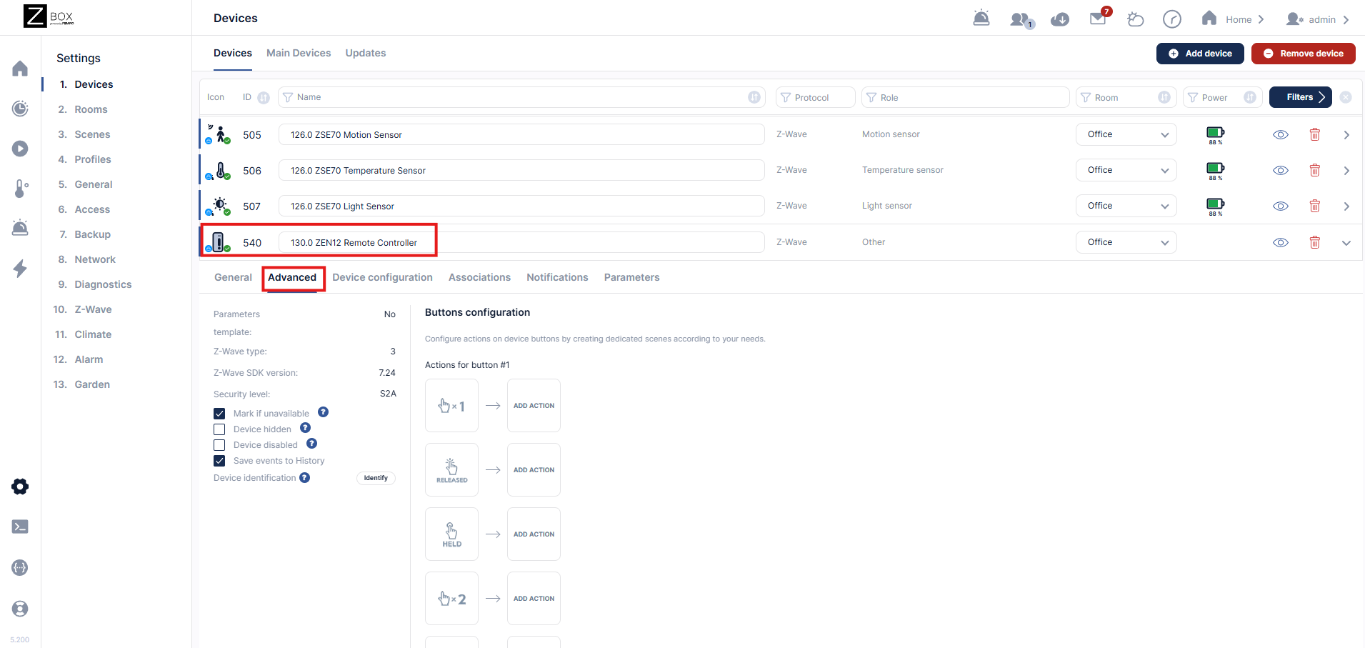
3. From the Button configuration menu, you can select the tap for your central scene trigger. Below we're using the single tap for our central scene trigger. The buttons are outlined above in the scene numbers and button mapping section.
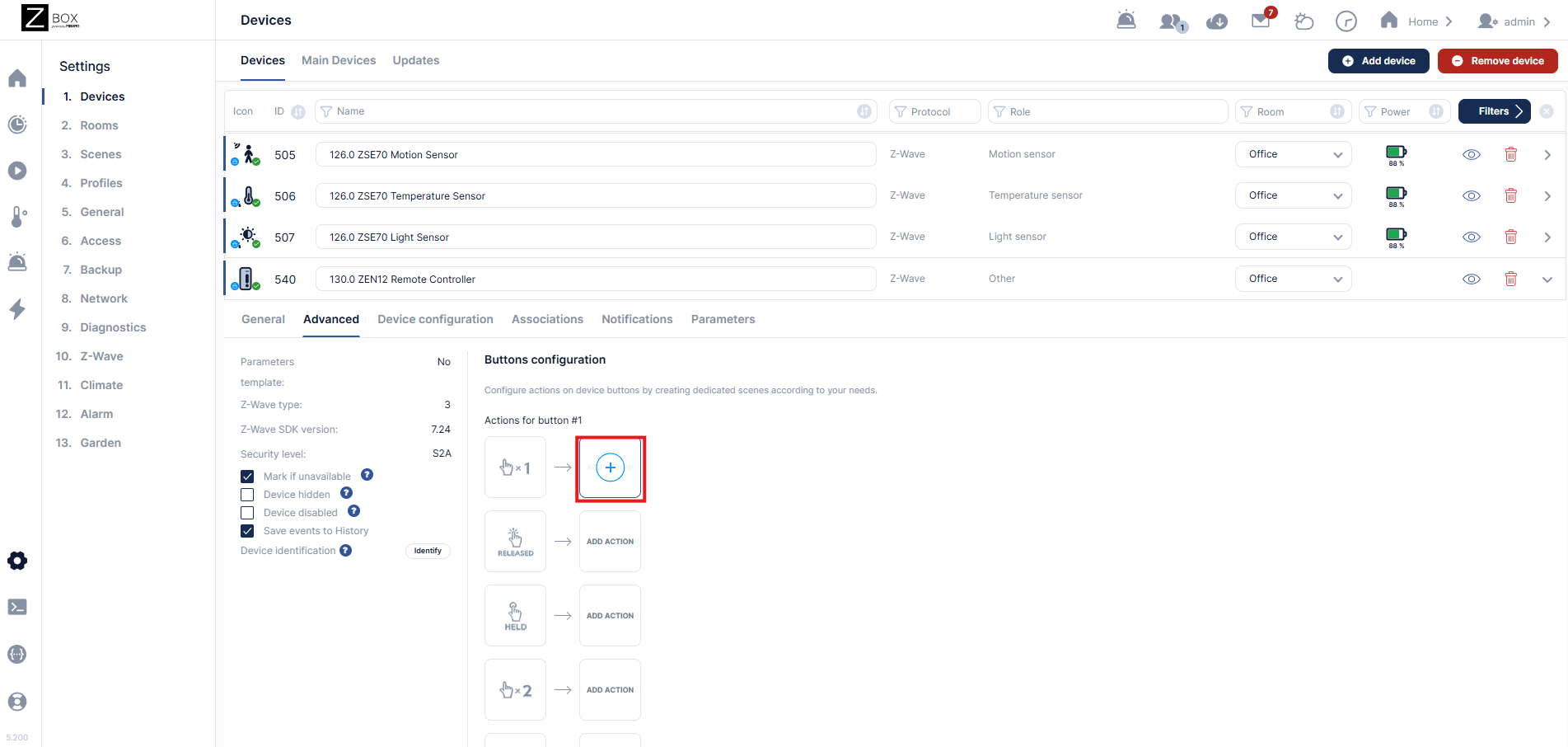
4. You will be redirected to the New Block Scene settings. Enter the required scene information and click Save. The selected button and trigger will be added automatically. You can change the trigger selection if needed. Drag the appropriate action tile to the “Do the following” section. Configure the action and click Save.

Direct Association
Direct association establishes a direct link between two Z-Wave devices, allowing one device to send commands directly to another without using a hub-based scene or automation.
For example, the ZEN12 can send on/off or dimming commands directly to another Z-Wave switch or dimmer. Its built-in motion and lux sensors can also send Basic Set commands directly to associated devices.
Direct association is best suited for simple, unconditional actions such as turning a device on or off or adjusting its brightness. The communication works in one direction. The ZEN12 sends a command to the associated device, but it does not receive status feedback from that device through the association.
Association Groups
The ZEN12 supports Group 1 with one device and Groups 2–6 with up to five devices in each group.
|
Group |
Command |
Function |
|---|---|---|
|
1 |
Lifeline and Basic Report |
Communication with the Z-Wave hub |
|
2 |
Basic Set |
Sends on/off commands when the ZEN12 is operated manually |
|
3 |
Multilevel Set |
Sends brightness-level commands to associated dimmers |
|
4 |
Multilevel Change |
Starts and stops dimming on associated devices when the ZEN12 dimming buttons are held and released |
|
5 |
Basic Set |
Sends on/off commands when the motion sensor is triggered or cleared |
|
6 |
Basic Set |
Sends on/off commands when the lux sensor changes between the configured night and day conditions |
-
Group 1 is assigned to the hub by default and should not be changed.
-
Use Group 2 to control an associated switch or dimmer with on/off commands from the ZEN12.
-
Groups 3 and 4 are intended for dimmers and smart bulbs that support Multilevel commands. Group 3 communicates the brightness level, while Group 4 allows the ZEN12 dimming buttons to start and stop brightness changes on the associated device.
-
Parameter 29 determines how long it takes an associated dimmer or smart bulb to move from 0% to 100% brightness when controlled through Groups 3 and 4.
-
Group 5 allows the built-in motion sensor to control another Z-Wave device directly. The timing of the motion-clear command is affected by the Motion Clear Delay configured in Parameter 17.
-
Group 6 allows the built-in lux sensor to control another Z-Wave device based on the configured night and day thresholds in Parameters 15 and 16.
Limitations and Considerations
Security level: Before programming direct association, ensure that the ZEN12 and the target device were added with the same Z-Wave security level. For example, an association may not be available or work correctly if one device was included with S2 Authenticated security and the other was included with S0 or without security.
Supported commands: The target device must support the command sent by the selected association group. Use Basic Set groups for on/off control and Multilevel groups for dimmers or other devices that support Multilevel commands.
One-way communication: Direct association does not provide status synchronization between the associated devices. The ZEN12 sends the command but does not check whether the receiving device successfully changed state.
Conditions and schedules: Direct association cannot evaluate additional conditions such as time, mode, presence, or the status of another device. Use a Z-Box scene instead if the action requires conditional logic.
Z-Wave Long Range: Direct association is not available when the ZEN12 is included using Z-Wave Long Range. Z-Wave Long Range devices communicate directly with the hub and do not communicate directly with other Z-Wave devices. Include the ZEN12 and target device using standard Z-Wave mesh if you plan to use direct association.
You can read more about the requirements, limitations, and recommendations for programming and using Direct Association here.
Programming Direct Association From the ZEN12 Device Menu
1. If you are not already on the Home Menu, open the sidebar navigation menu in the Z-Box web interface and click the house icon. Hover over the ZEN12 Motion Dimmer, then click the settings gear icon.
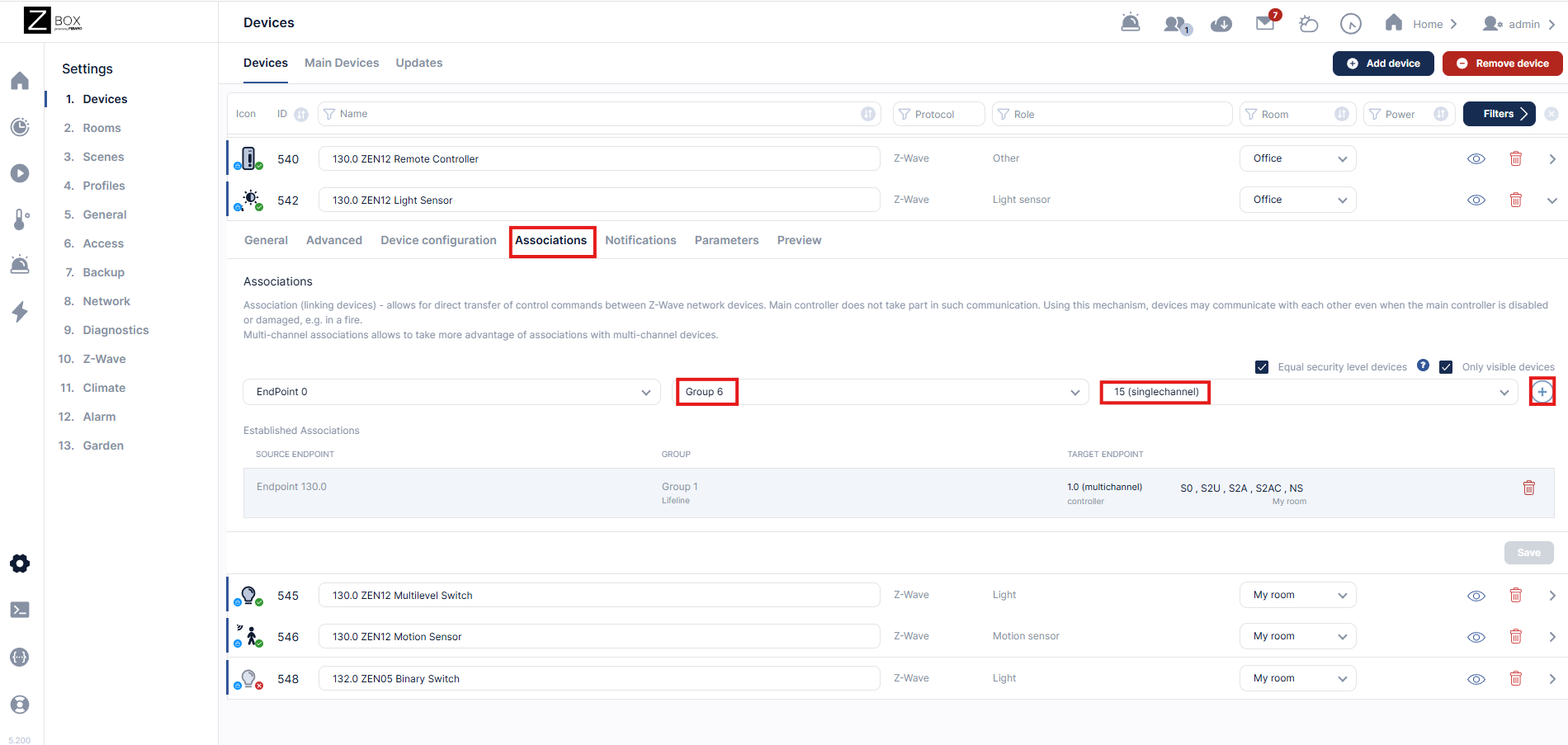
2. Click the Associations tab. For this example, we'll be setting the association from the lux sensor on the ZEN12:
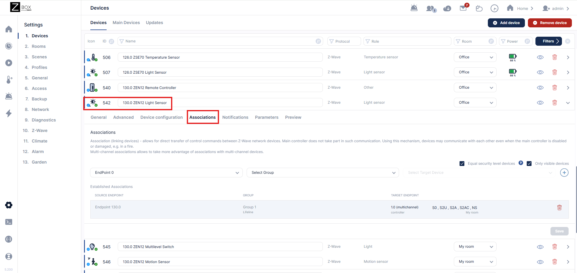
Select the appropriate association group for the function you would like to program:
-
Group 2 for manual on/off control
-
Group 3 for brightness-level control
-
Group 4 for start/stop dimming
-
Group 5 for motion-triggered on/off control
-
Group 6 for lux-triggered on/off control
Select the target device and click the + symbol. Click Save to complete the association.
LED Indicator Programming
The ZEN12 includes a customizable LED indicator that can display the status of the connected load, remain permanently on or off, or display different colors based on the dimmer’s current state.
The LED’s regular behavior is configured through the ZEN12 advanced settings.
LED Behavior
Parameter 1 determines when the primary LED color is displayed:
|
Value |
LED Behavior |
|---|---|
|
|
LED on when the connected light is off |
|
|
LED on when the connected light is on |
|
|
LED always off |
|
|
LED always on |
Default: 0
Primary LED Color
Parameter 2 determines the primary LED color:
|
Value |
Color |
|---|---|
|
|
White |
|
|
Blue |
|
|
Green |
|
|
Red |
|
|
Yellow |
|
|
Cyan |
|
|
Magenta |
Default: 0, white
LED Brightness
Parameter 3 determines the LED brightness:
|
Value |
Brightness |
|---|---|
|
|
10% |
|
|
20% |
|
|
30% |
|
|
40% |
|
|
50% |
|
|
60% |
|
|
70% |
|
|
80% |
|
|
90% |
|
|
100% |
Default: 5, 50%
Displaying Two Colors Based on the Load Status
Parameter 45 allows the LED to display a second color instead of turning off during the opposite switch state.
For example, you could configure the indicator to display green when the connected light is on and red when it is off.
|
Value |
Opposite-State Color |
|---|---|
|
|
Off |
|
|
White |
|
|
Blue |
|
|
Green |
|
|
Red |
|
|
Yellow |
|
|
Cyan |
|
|
Magenta |
Default: 0, off
For example, to display green when the connected light is on and red when it is off:
-
Set Parameter 1 to
1, LED on when the light is on. -
Set Parameter 2 to
2, green. -
Set Parameter 45 to
4, red.
The LED will display green when the connected load is on and red when it is off.
Scene Indicator
Parameter 9 controls whether the LED provides temporary visual feedback when a Central Scene command is triggered:
-
0: Scene indicator disabled -
1: Scene indicator enabled
Default: 0
When enabled, the LED identifies the button and type of Central Scene event:
|
Button |
Scene Indicator Color |
|---|---|
|
Main Button |
White |
|
Left Button |
Blue |
|
Right Button |
Green |
|
ZAC99 Remote Button |
Red |
The number of illuminated indicator segments corresponds to the number of taps:
-
One tap: one segment illuminated for two seconds
-
Two taps: two segments illuminated for two seconds
-
Three taps: three segments illuminated for two seconds
-
Four taps: four segments illuminated for two seconds
-
Five taps: five segments illuminated for two seconds
-
Held: left and right segments illuminated for two seconds
This temporary scene feedback is separate from the normal LED color and status behavior configured through Parameters 1–3 and 45.
Additional LED Settings
The following settings also affect LED operation:
-
Parameter 23: Determines whether the LED flashes to confirm a configuration-setting change.
-
Parameter 42: Determines whether the ZEN12 reports status and changes its LED when physical load control is disabled.
Refer to the ZEN12 Motion Dimmer Advanced Settings for the complete parameter descriptions and available values.
Controlling the LED From Automations
The ZEN12 LED can be configured to reflect the status of its own connected load through the advanced settings described above. However, the Z-Box does not currently support changing ZEN12 configuration parameters dynamically through standard block scenes.
If you want the LED to reflect the status of a different device or serve as a customizable notification indicator, you will need to create a Lua scene.
Lua programming is intended for advanced users familiar with the Z-Box scene environment. The device IDs, parameter numbers, and parameter values must be customized for the individual installation. We are not able to provide custom coding instructions outside of our example.
The example below monitors another switch and changes the ZEN12 LED to green when that switch is on and red when it is off.
-- Scene: Set the ZEN12 LED based on another switch's status
-- Description: Display green when the monitored switch is on
-- and red when the monitored switch is off.
-- Enter the device ID of the switch being monitored
local switchID = 1
-- Enter the device ID of the ZEN12
local zen12ID = 2
-- Read the current state of the monitored switch
local switchState = tonumber(
fibaro.getValue(switchID, "value")
) or 0
-- Keep the ZEN12 LED illuminated
-- Parameter 1, size 1, value 3 = LED always on
fibaro.call(
zen12ID,
"setConfiguration",
1,
1,
3
)
-- Change the LED color based on the monitored switch status
if switchState > 0 then
-- Parameter 2, size 1, value 2 = green
fibaro.call(
zen12ID,
"setConfiguration",
2,
1,
2
)
else
-- Parameter 2, size 1, value 3 = red
fibaro.call(
zen12ID,
"setConfiguration",
2,
1,
3
)
end
Replace the example device IDs as follows:
-
switchID: The Z-Box device ID of the switch or dimmer being monitored. -
zen12ID: The Z-Box device ID assigned to the ZEN12.
The configuration command uses the following format:
fibaro.call(
deviceID,
"setConfiguration",
parameterNumber,
parameterSize,
parameterValue
)
In this example:
-
Parameter 1 is set to value
3so the ZEN12 LED remains on. -
Parameter 2 is set to value
2to display green when the monitored device is on. -
Parameter 2 is set to value
3to display red when the monitored device is off.
The Lua scene must be triggered whenever the monitored device changes state.
If you do not want the LED to flash each time a configuration parameter is changed, add the following command:
-- Parameter 23, size 1, value 1 =
-- disable the parameter-change confirmation flash
fibaro.call(
zen12ID,
"setConfiguration",
23,
1,
1
)
You can substitute other supported Parameter 2 values to use different LED colors. Refer to the ZEN12 Motion Dimmer Advanced Settings for the complete parameter descriptions and available values.
Please let us know if you have any questions!

